Creating a Load Balancer Using Oracle Cloud Infrastructure Load Balancing
Before You Begin
This tutorial shows you how to create a simple load balancer and verify it with a basic web server application. This tutorial takes approximately 45 minutes to complete.
Background
A load balancer provides automated traffic distribution from one entry point to multiple servers reachable from your Virtual Cloud Network (VCN) and allows you to create highly available resources within your VCN. Oracle Cloud Infrastructure Load Balancing offers a load balancer with your choice of a public or private IP address and provisioned bandwidth and availability features across two Availability Domains. It improves resource utilization, facilitates scaling, and helps ensure high availability. Oracle Cloud Infrastructure Load Balancing also supports handling of both incoming and outgoing Secure Sockets Layer (SSL) traffic.
Two web servers (such as Apache HTTP Server) running on each instance, Webserver1 and Webserver2, with the following:
Firewalls opened to allow HTTP and HTTPS traffic.
An index.htm file created on each web server (Webserver1 and Webserver2) containing the text "WebServer1" and Webserver2" respectively.
Add Subnets to Your VCN to Host Your Load Balancer
Your load balancer should always reside in a separate subnet than your application instances. This allows you to keep your application instances secured in private subnets while allowing public Internet traffic to the load balancer in the public subnets.
To add the public subnets to your VCN perform the following tasks:
Add a security list.
Add a route table.
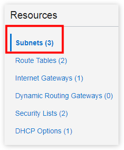
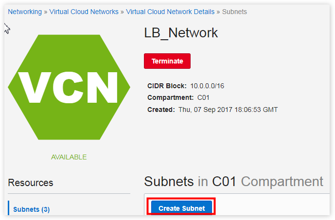
Create the first and second subnets.
Add a Security List
In the console, click Networking, and then click Virtual Cloud Networks.
The list of VCNs in the current compartment is displayed.
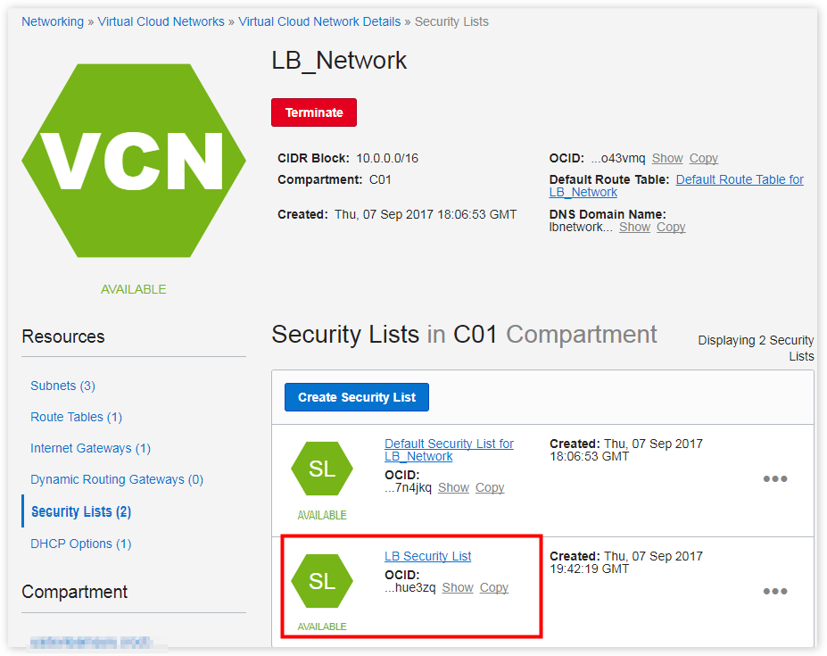
Click the name of the VCN, such as LB_Network, which includes your application instances.
In the Security Lists page, click Create Security List.
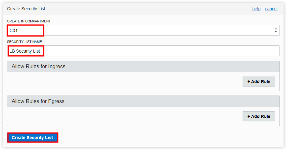
In the Create Security List dialog box, enter the following:
CREATE IN COMPARTMENT: Select the compartment you want to create the security list in, if not already selected. In this example, select C01. This field defaults to your current compartment.
SECURITY LIST NAME: Enter a Name, for example, LB Security List.
Delete the entries for the ingress rule and the egress rule.
The security list should have no rules. The correct rules will be automatically added in the load balancer workflow.
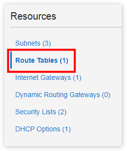
In the Route Tables page, click Create Route Table.
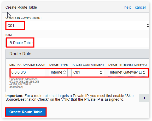
In the Create Route Table dialog box, enter the following:
CREATE IN COMPARTMENT: Select the compartment you want to create the security list in, if not already selected. In this example, select C01. This field defaults to your current compartment.
NAME: Enter a Name, for example, LB Route Table.
DESTINATION CIDR BLOCK: Enter 0.0.0.0/0.
TARGET TYPE: Select Internet Gateway.
Note: The TARGET COMPARTMENT field is automatically populated.
TARGET INTERNET GATEWAY: Select the Internet Gateway for your VCN, which is the Internet Gateway LB_Network.
Similarly, create the second subnet. However, for the second subnet, enter the following for NAME, AVAILABILITY DOMAIN, and the CIDR BLOCK fields:
NAME: Enter a name, for example, LB Subnet 2.
AVAILABILITY DOMAIN: Choose the first Availability Domain such as OBze:PHX-AD-2.
CIDR BLOCK: Enter 10.0.5.0/24.
Create the Load Balancer
When you create a load balancer, you first choose its shape (size) and then select two subnets in different Availability Domains. This ensures high availability and that the load balancer is active only in one subnet at a time. This load balancer comes with a public IP address and provisioned bandwidth corresponding to the shape you chose.
In the console, click Networking, and then click Load Balancers.
A backend set is a collection of backend servers to which your load balancer directs traffic. In this tutorial, you will create one backend set that includes your two web servers.
A new browser window opens displaying the instances in the current compartment.
If your instances are not in the current compartment, select the compartment to which the instance belongs. In this example, you've created the instances in current compartment, C01.
A shortened version of the OCID is displayed next to each instance.
Click Copy to copy the OCID.
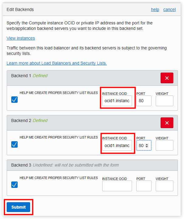
Return to the browser window displaying the Edit Backends dialog box and paste the copied OCID into the Instance OCID field.
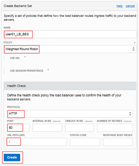
PORT: Enter 80.
WEIGHT: Leave this field blank. The system will distribute the weight on the servers evenly.
Repeat Steps 2 through 4 to add the details of the second backend server (the second instance, Webserver2).
A listener is an entity that checks for connection requests. The load balancer listener listens for ingress client traffic (using the port that you specify) within the listener and the load balancer's public IP.
In this tutorial, you'll define a listener that accepts HTTP requests on port 80.
Go to your Load Balancer Details page, click Listeners on the left.
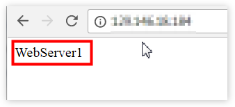
Now that the load balancer is fully configured, you can test its functionality by navigating to its public IP address on a web browser. If the load balancer has been configured properly, you should see the name of one of the web instances.
Open a web browser.
Enter the load balancer public IP address in the address bar and press Enter.
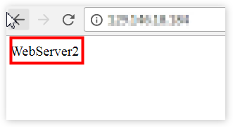
The index.htm page of the other web server should now be displayed.
Description of the illustration webserver2.png
Because you configured the load balancer backend set policy as round robin, refreshing the page will alternate between the two web servers.
 Creating a Load Balancer Using Oracle Cloud Infrastructure Load Balancing
 Before You Begin
 Add Subnets to Your VCN to Host Your Load Balancer
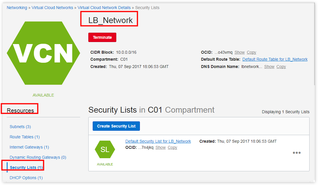

 Create the Load Balancer

 Create a Backend Set
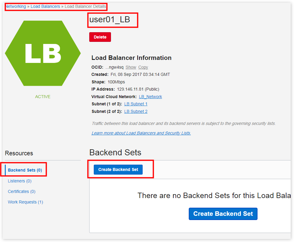
 Add Backends (Servers) to Your Backend Set
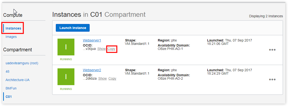

 Create the Listener for Your Load Balancer
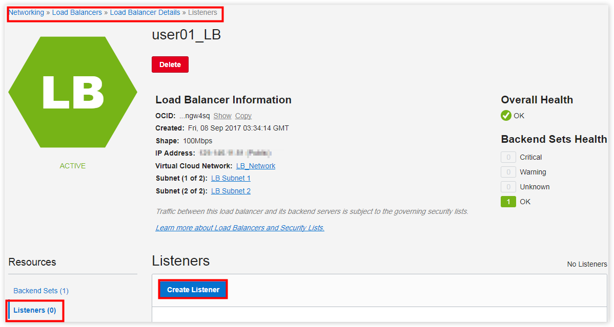

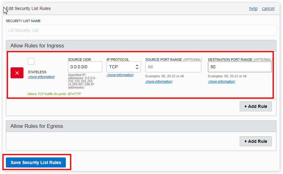
 Update Load Balancer Security Lists to Allow Internet Traffic to the Listener
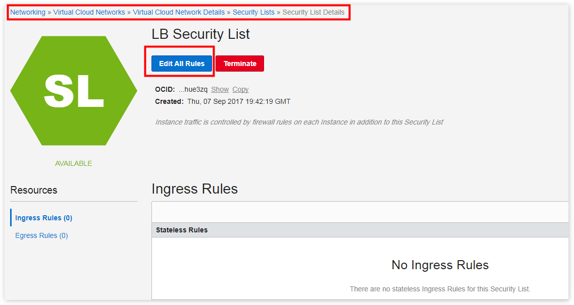
 Verify Your Load Balancer