Working with UART by Using Java ME Embedded and a Raspberry Pi
Overview
Purpose
This tutorial covers how to create an Oracle Java Micro Edition Embedded 8 (Java ME Embedded 8) application that read and write to a universal asynchronous receiver/transmitter (UART) device. When connected to a Raspberry Pi, the UART device reads data from global position system (GPS) satellites to provide an accurate position.
Time to Complete
Approximately 1 hour
Introduction
Intelligent devices are becoming an ever more important and ubiquitous part of our everyday lives. Mobile phones represented the first wave of smaller personal computers. And now, as the price of electronics and processing power continues to fall, there is an intersection between sensors and other electromechanical devices and computers that live on the edge of the Internet: close to the source of the data, processing the data locally and sending just what is required to other computers to consume. This wave of machine-to-machine (M2M) technology, or more broadly, the Internet of Things (IoT), is rapidly shaping the future of computing. Oracle Java Platform, Micro Edition (Java ME) provides Java developers with a direct path to this new market space by using their existing knowledge and skills.
The serial connection is the mainstay of communications between computer equipment and terminals and keyboards. The advantage of serial communications is the simplicity of the wiring and the ability to communicate in both synchronous and asynchronous modes. Serial devices typically have an integrated circuit (stand-alone or part of another hardware) called a UART, which handles the specific signaling required to establish communications and convert digital signals to individual characters. The Raspberry Pi has a built-in UART that can be used to communicate with serial devices, including the Adafruit GPS device, which uses serial communication to send GPS telemetry data to the Raspberry Pi.
Scenario
In this tutorial, you create a Java ME Embedded 8 application that communicates with a GPS device. The device provides accurate positioning by using global positioning satellites. You use a MediaTek MT3339 chipset, which was designed for small, hand-held and mobile GPS applications. The chip is soldered on a breakout board that includes supporting components to make it compatible with the Raspberry Pi.
Hardware and Software Requirements
The following is a list of hardware and software requirements:
- Adafruit Ultimate GPS Breakout (or equivalent)
- (Optional) USB to TTL serial cable
- Raspberry Pi Cobbler Kit or equivalent general-purpose input/output (GPIO) header to breadboard connector
- Breadboard
- Breadboard wires
Prerequisites
Before starting this tutorial, you should:
- Have completed the Oracle By Example tutorial titled: Configuring the Raspberry Pi as an Oracle Java ME Embedded Platform.
- Have completed the Oracle By Example tutorial titled Working with GPIO By Using Java ME Embedded and a Raspberry Pi.
- Purchase the hardware required for the tutorial.
- Solder wires or a header to the GPS breakout board. See this tutorial for more information.
Installing the GPS Daemon Software (gpsd)
In this section, you install gpsd, a tool that
allows you to quickly test the functionality of your GPS device.
-
Connect to the Raspberry Pi by using PuTTY.

-
Enter sudo apt-get install gpsd gpsd-clients python-gps to install the
gpsddaemon and clients.
-
Enter Y at the prompt.

The software takes a few minutes to install.

(Optional) Connecting the GPS Device by Using the USB to TTL Serial Cable
If you have a USB to TTL serial cable, you can test the GPS device without creating a circuit on the breadboard. Note: USB line voltages are 5V, which is too high for typical TTL devices. This custom cable converts the 5V levels to TTL levels that are compatible with serial devices.
-
Attach the ends of the USB to TTL serial cable to the GPS breakout module in the following sequence:
- Connect the red lead to the VIN pin of the GPS device.
- Connect the black lead to the GND pin.
- Connect the green lead to the RX pin.
- Connect the white lead to the TX pin.

-
Plug the USB end into the Raspberry Pi.

For the first few minutes, the Fix LED on the GPS breakout board will flash about once every second while it is acquiring a signal. After it acquires a signal, the Fix LED will flash every 15 seconds.
-
Enter ls /dev/ttyUSB* to determine the device's USB port connection.

In this example, the GPS device is on the
/dev/ttyUSB0serial port. -
Enter sudo gpsd /dev/ttyUSB0 -F /var/run/gpsd.sock to start the
gpsddaemon on the device address.
Note: Use the USB serial port that you located in step 3.
-
Enter cgps -s to start the GPS client and display the output.

Formatted data from the GPS device is displayed in the console window.

-
If there is no output and
cgpsquits after just a few seconds, perform the following steps:- Place the GPS device close to a window. In general, GPS works better with a line of sight to the sky.
- Wait for the device to acquire a fix. This may take a few minutes, depending upon your location.
- Enter cat /dev/USB0 in the PuTTY window (use the USB port number you discovered in step 3). You should see strings of characters. If not, recheck your connections.
- Kill and restart the
gpsddaemon.
Connecting the GPS Device by Using the UART on the Raspberry Pi
By default, the Raspberry Pi uses its built-in UART as the serial console. Therefore, you must configure the Raspberry Pi so that you can use the UART.
Creating the Application Circuit by Using the Breadboard
-
Place the 26-pin header connector into the breadboard so that:
- The connector straddles the center.
- Pin 1 (marked 3V3) is in column 14 at the top.
- The "key" (the square cutout in the center of the connector) is in the center at the top.

Note: Your breadboard may be different. Leave enough room to place the GPS device to the left of the connector.
-
Insert the GPS breakout board into the breadboard so that the breakout board's left pin (PPS) is in row 1.

All of the breakout board's pins should be in column f.
-
Check that you have version 2 of the Raspberry Pi. For more information, see "Checking the Hardware Version of Your Raspberry Pi" in the tutorial titled Working with GPIO by Using Java Embedded and a Raspberry Pi.
-
Perform the following tasks, using the row numbers shown in the image as a reference:
- Insert a red wire between row 2, marked VIN on the GPS
breakout board, and row 14 on the connector (marked
5v0).
Note: Because the GPS device has an internal voltage regulator, you can wire it to the 5V output line. - Insert a green wire between row 3, marked GND on the GPS breakout board, and row 16 on the connector (marked GND) .
- Insert a blue wire between row 4, marked RX on the GPS breakout board, and row 17 on the connector (marked TXD).
- Insert a white wire between row 5, marked TX on the GPS breakout board, and row 18 on the connector (marked RXD).

Note: You are cross-wiring the RX pin on the GPS device to the TXD pin on the connector, and the TX pin on the GPS device to the RXD pin on the connector.
Your wiring should look similar to this picture:

- Insert a red wire between row 2, marked VIN on the GPS
breakout board, and row 14 on the connector (marked
5v0).
-
Review the application circuit that you created.
-
Unplug the Raspberry Pi power cable .
-
Connect the ribbon cable between the breadboard and the Raspberry Pi.
If you have not performed this step before, see "Connecting the Ribbon Cable Between the Raspberry Pi and the Header" in the tutorial titled Working with GPIO by Using Java Embedded and a Raspberry Pi.
-
Plug the power cable back into your Raspberry Pi.

Note: It is important that you cross-connect the RX pin on the GPS device to the TXD pin on the connector and the TX pin on the GPS device to the RXD pin on the connector.
Configuring the UART on the Raspberry Pi
-
Connect to the Raspberry Pi by using PuTTY.
-
Enter sudo nano /boot/cmdline.txt.

-
Remove
console=ttyAMA0,115200
                          kgdboc=ttyAMA0,115200
from the first line in the file.
-
Press Ctrl + O and Enter, and then press Ctrl + X to write and close the file.

-
Enter sudo nano /etc/inittab.

-
Perform the following steps:
- Comment out the last line (enter a # at the beginning of the line).
- Press Ctrl + O and Enter to write the file.
- Press Ctrl + X to close the file.

At this point, you have released the
/dev/ttyAMA0UART serial port. -
Enter sudo reboot to reboot the Raspberry Pi and make the changes.

-
After a few minutes, right-click in the PuTTY window and select Restart Session to reconnect to the Raspberry Pi.

-
Log in with the user id pi and the password raspberry.

-
Enter sudo gpsd /dev/ttyAMA0 -F /var/run/gpsd.sock to start the
gpsddaemon on the UART serial port (/dev/ttyAMA0).
-
Enter cgps -s to display the GPS data.

Formatted data from the GPS device is displayed in the console window.
The GPS device is writing correctly to the UART connection.
Creating a Java ME Project That Uses the GPS Device
In this section, you use NetBeans to develop a Java ME application that reads the GPS device output to the UART serial port. Note: The code in this tutorial is provided in the Resources section.
Creating a NetBeans Java ME Embedded Project
-
Select File > New Project.

-
Select Java ME Embedded from Categories and Java ME Embedded Application from Projects and click Next.

-
In the New Java ME Embedded Application dialog, perform the following steps:
- Enter
GPSExampleas the Project name. - Select EmbeddedExternalDevice1 as the Java ME Platform.
- Enter com.example.GPSIMlet in the Create Midlet field.
- Click Finish.

- Enter
Setting Security API Permissions
Java ME Embedded projects that use UART and Comm devices must set special API permissions.
-
Right click the Project and select Properties.

-
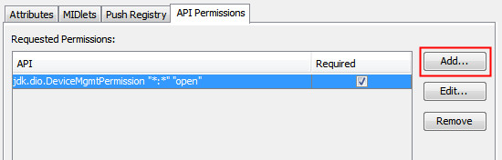
Click the Application Descriptor category and select to the API Permissions tab. Click Add.

-
In the Add Permission dialog:
- Select jdk.dio.DeviceMgmtPermission from the drop-down menu list.
- Enter *:* as the protected resource name.
- Enter open in the Actions Requested field.
- Click OK.

-
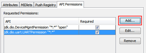
Click Add to add another permission for a UART connection.
-
In the Add Permission dialog:
- Select jdk.dio.uart.UARTPermission from the drop-down menu.
- Enter *:* as the protected resource name.
- Click OK.

-
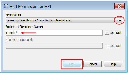
Click Add to add another permission for a Comm Connection.
-
In the Add Permission dialog:
- Select javax.microedition.io.CommProtocolPermission from the drop-down menu.
- Enter comm:* as the protected resource name.
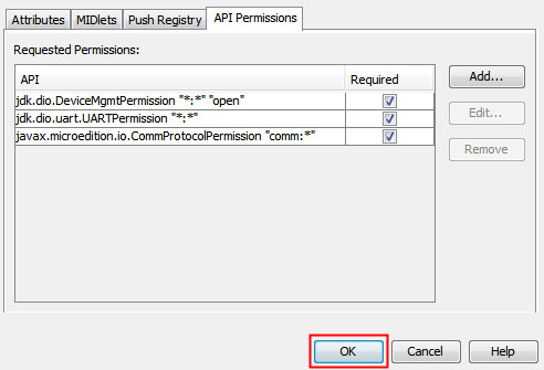
- Click OK.
-
Click Ok to close the properties dialog.
Adding The Provided Classes to the GPSExample Project
-
Expand the classes.zip file provided in the Resources section.
- Copy the files GPSCommSensor.java, GPSSensor.java, GPSUARTSensor.java, Position.java.
-
In NetBeans, right-click on the
com.examplepackage and select Paste to paste the files into the project.
There should be five files in the
com.examplepackage.
-
Open the
GPSSensorclass and note that it is an abstract class. This class provides the base functionality for the GPS sensor, but must be implemented by another class to be instantiated. -
Open the
GPSUARTSensorandGPSCommSensorclasses. These classes provide the specific protocol support for the sensor, as a comm-port device or UART device respectively. -
Open the
Positionclass. Note that this class is a POJO, but provides a valuable method for converting the NMEA strings to degree/minute/second position values.
Implementing the GPSIMlet class
-
Add the following class field:
private static final String SERIAL_PORT = "ttyAMA0"; -
Implement the
startAppmethod.@Override public void startApp() { try (GPSUARTSensor gps = new GPSUARTSensor()) { //try (GPSCommSensor gps = new GPSCommSensor(SERIAL_PORT)) { /* Take one reading every second for 10 readings */ for (int i = 0; i < 10; i++) { Position p = gps.getPosition(); // Use the toString method to print the result System.out.println(p + "\n"); Thread.sleep(1000); } } catch (IOException ioe) { System.out.println("GPSTestMidlet: IOException " + ioe.getMessage()); } catch (InterruptedException ex) { // Ignore } /* Terminate the Imlet correctly */ System.out.println("GPSTestMidlet finished"); notifyDestroyed(); }This method creates an instance of
GPSUARTSensorobject in a try-with-resources block. When the try ends, theclosemethod will automatically get called, obviating the need for thedestroyAppmethod. -
Fix any missing import statements and save the file.
Running and Testing the GPSExample Project on the Raspberry Pi
In this section, you test the application by using NetBeans with the application circuit that you wired.
-
Perform the following steps:
- Connect to your Raspberry Pi with PuTTY.
- Change directories with the cd javame8/bin command.
- Start the Application Management System with the sudo ./usertest.sh command.

-
In NetBeans, right-click the
GPSExampleproject and select Run.
In the Output Console of the EmbeddedExternalDevice1 emulator, the data read from the GPS sensor is displayed..

Note: If nothing is displayed and the application appears to hang, check and make sure you have the 8.1 EA version of the Java ME Embedded 8 binary for Raspberry Pi. The GA version of the binary will not work with this GPS device.
-
Click Stop in the emulator to stop the application.

- In the GPSIMlet, try commenting out the try-with-resources
that opens the GPS as a UART and uncomment the line that opens
the GPS as a comm port:
public void startApp() { //try (GPSUARTSensor gps = new GPSUARTSensor()) { try (GPSCommSensor gps = new GPSCommSensor(SERIAL_PORT)) { -
Run the project again.
Summary
In this tutorial, you learned to:
- Install the
gpsddaemon and client software - Connect the GPS device by using a USB to TTL serial cable
- Prepare the Raspberry Pi to use the UART
- Connect the GPS device to the Raspberry Pi's UART
- Write a Java ME Embedded 8 EA application by using the GCF to read the UART
Resources
- GlobalTop Technology for MTK3339 GPS Module Data Sheet
- GlobalTop Technology for MK3339 GPS command set sheet ("PMTK Command Packet")
- Class files
- The National Marine Electronics Association specification
- To learn more about Java Embedded, refer to additional OBEs in the Oracle Learning Library
Credits
- Lead Curriculum Developer: Tom McGinn
- Other Contributors: Edgar Alberto Martinez Cruz
To navigate this Oracle by Example tutorial, note the following:
- Topic List:
- Click a topic to navigate to that section.
- Expand All Topics:
- Click the button to show or hide the details for the sections. By default, all topics are collapsed.
- Hide All Images:
- Click the button to show or hide the screenshots. By default, all images are displayed.
- Print:
- Click the button to print the content. The content that is currently displayed or hidden is printed.
To navigate to a particular section in this tutorial, select the topic from the list.